
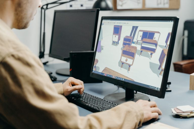
A 3D model can look perfect in Blender and still fail spectacularly when printed. A missing surface might leave a hole in the object. Incorrect scaling can turn a small bracket into something the size of a dinner plate. An unsupported overhang can produce a tangled mess of plastic.
Most of those problems are preventable. Blender helps you prepare the geometry, and slicing software such as Cura or PrusaSlicer converts the finished model into instructions a printer can follow.
For this walkthrough, we will use a small desk cable holder as an example. The same preparation process applies to decorative objects, prototypes, replacement parts and many other models printed with filament.
Blender, Cura and PrusaSlicer Have Different Jobs
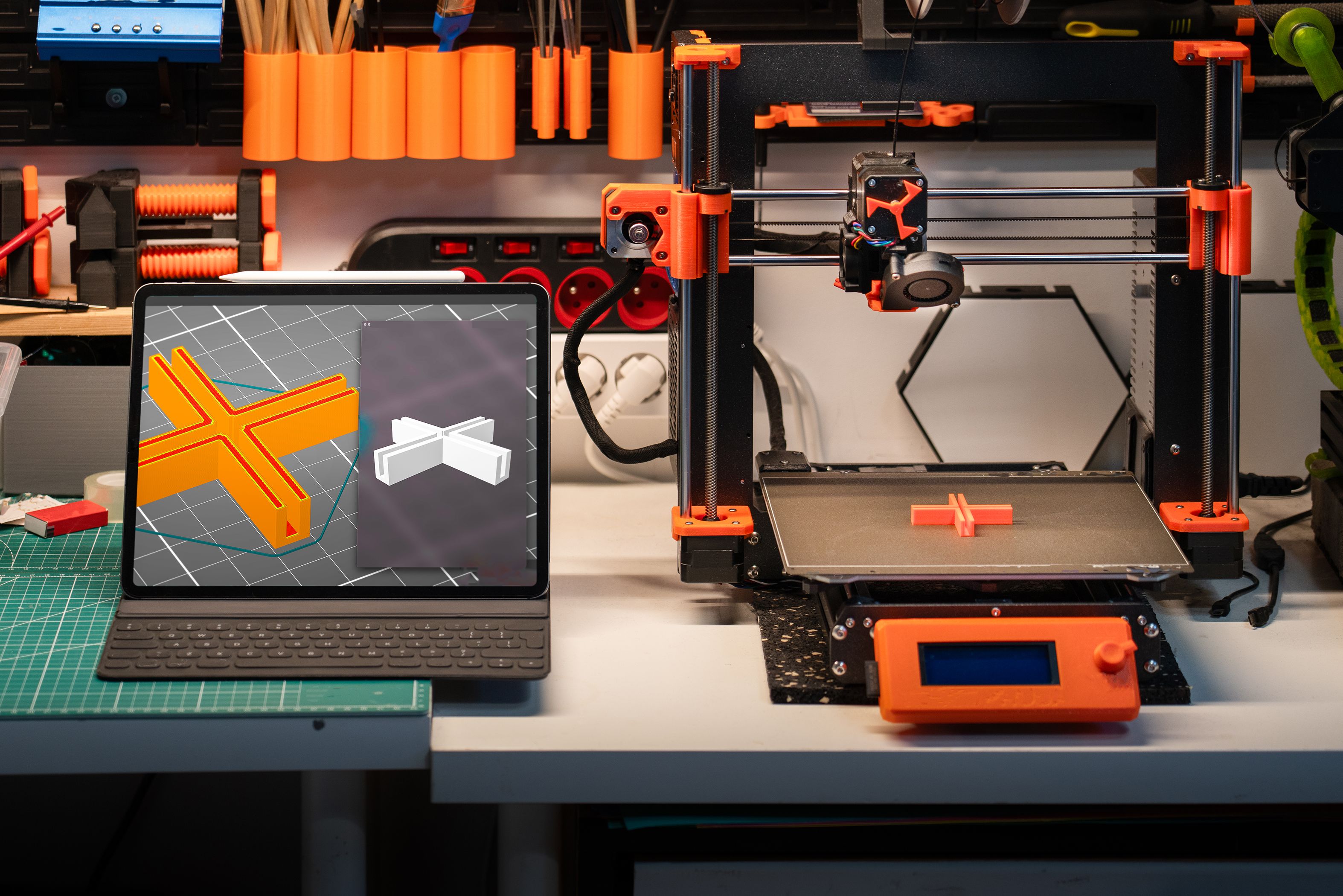
A prepared digital model moves from Blender into a slicer before it reaches the printer.
You do not need all three applications for every print. Blender handles modeling, and you can choose Cura or PrusaSlicer to prepare the actual printing instructions.
A useful way to organize the work is to finish the model in Blender before adjusting the printing settings. Changing a broken object into a printable one is generally easier in the modeling software than trying to repair every problem in the slicer.
Step 1. Build Your Model Using Real Dimensions in Blender
Begin with the intended dimensions of the finished object.
For example, suppose your cable holder needs to measure 60 mm long, 20 mm wide and 12 mm high. Those numbers should guide the model rather than estimating its size visually.
Open Blender and select Scene Properties. Under Units, choose Metric and configure a suitable length display. You can then enter precise dimensions through the Item panel, available with the N shortcut in the 3D Viewport.
Use the Transform panel to check the dimensions after changing the geometry.
Blender also allows objects to be scaled without changing their underlying mesh coordinates. Before exporting, select the object in Object Mode and use Ctrl + A followed by Scale to apply its scale.
Applying scale helps prevent unexpected behavior with modifiers and makes the object easier to inspect. It does not replace checking the export units and final dimensions inside the slicer.
Step 2. Check the Mesh for Holes and Broken Geometry
A model intended to represent a solid object needs geometry that the slicing software can interpret correctly.
One common problem is a non-manifold mesh. For a simple solid, that can mean an open edge, missing face or internal surface that prevents the model having an unambiguous enclosed volume.
Consider a rectangular box with its bottom face accidentally deleted. Blender can still display the remaining surfaces, but the model no longer describes a closed solid.
Find Mesh Problems in Blender
Open the object in Edit Mode, switch to edge selection and use Select > Select All by Trait > Non-Manifold.
Blender will highlight edges associated with certain geometry problems. Inspect those areas and repair them rather than deleting geometry at random.
You can also install the official 3D Print Toolbox extension. It provides tools for checking geometry, calculating volume and identifying potential printing problems.
The extension includes a Make Manifold function, although automated repairs should always be inspected afterward.
For our cable holder, check that the base and curved retaining section form the intended solid. Accidental gaps or overlapping internal faces can produce unexpected results during slicing.
Check the Surface Normals
Every mesh face has a normal indicating its orientation.
Incorrectly oriented faces can confuse operations that depend on identifying the inside and outside of an object.
In Blender, open the Viewport Overlays menu and enable Face Orientation. Exterior faces should normally appear blue, with reversed faces displayed in red.
Select the affected geometry in Edit Mode and press Shift + N to recalculate normals.
Check the result visually. Automatic recalculation cannot resolve every case involving complicated or intersecting geometry.
Step 3. Check Wall Thickness and Small Details
A thin wall may look perfectly acceptable on screen but disappear during slicing.
Imagine adding a decorative ridge that measures only 0.1 mm across. A typical 0.4 mm FDM nozzle may be unable to reproduce it as intended, depending on the slicer and print settings.
For functional parts, wall thickness also affects strength. A cable holder needs enough material around the retaining arm to withstand repeated bending or pressure.
If your model consists of surfaces without thickness, Blender has a Solidify modifier that can add material thickness.
For an existing solid, inspect the narrowest features and compare them with the nozzle and intended extrusion widths.
Do not assume that increasing infill will repair a wall that is too thin. The outer geometry must be printable first.
Step 4. Export the Model in a Suitable Format
Once the geometry is ready, export the model for slicing.
STL is widely supported and works well for ordinary single-material models. It stores the object as triangles describing its surface.
In Blender, select the finished model and choose File > Export > STL. Enable Selection Only if you want to exclude cameras, lights and unrelated objects.
Check the scaling and unit options. The Blender STL documentation explains the available export settings, including scene units and applying modifiers.
For example, a model intended to measure 60 mm should still measure 60 mm when imported into Cura or PrusaSlicer.
STL does not store measurement units, so the receiving application must interpret the coordinates correctly. An unexpected size is a reason to review the export settings before printing.
Step 5. Import Your Model Into Cura
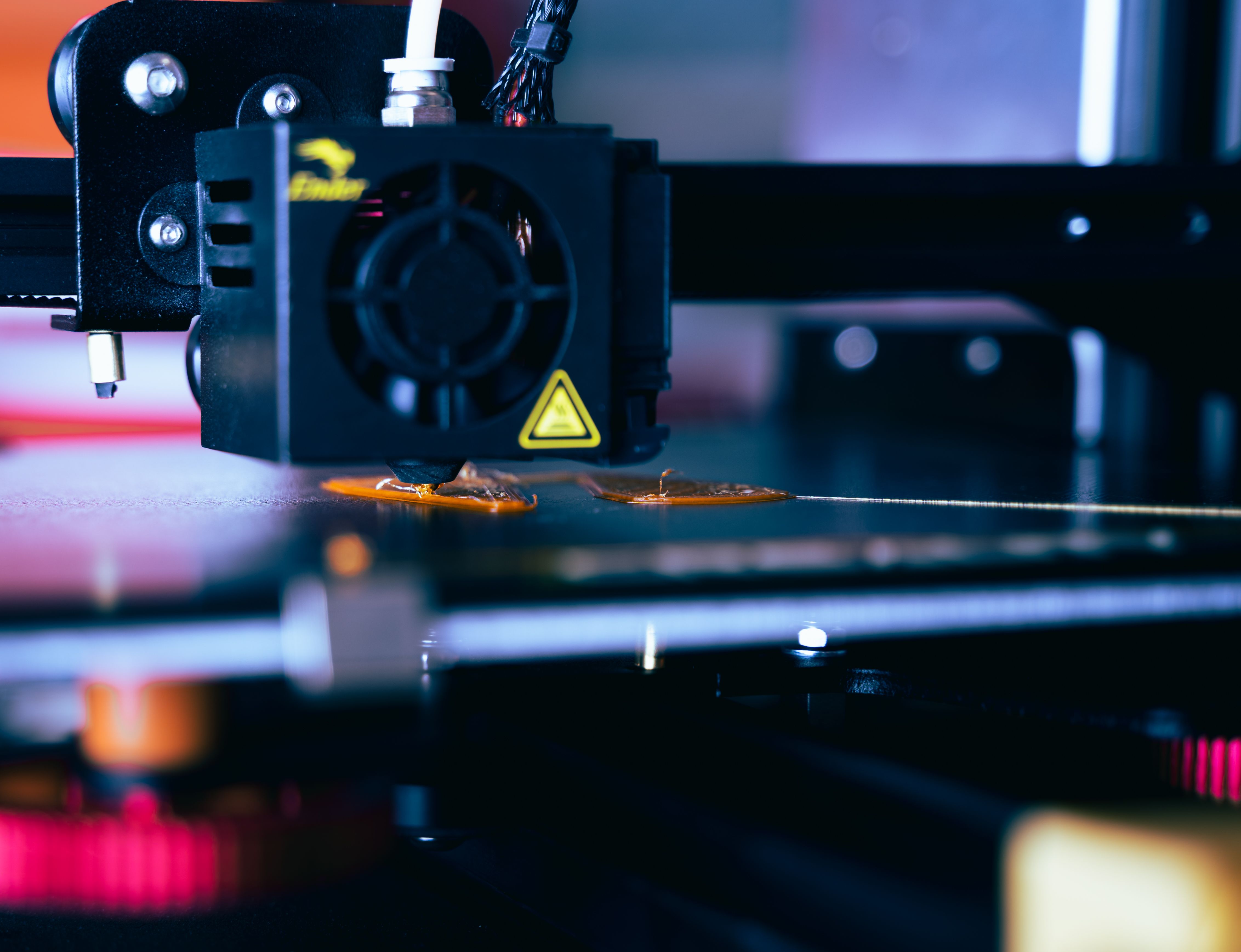
The slicer translates the model into paths that the printer nozzle follows, one layer at a time.
Open UltiMaker Cura and choose the printer that will produce your object.
The machine profile is important because it defines information such as build dimensions, nozzle configuration and compatible printing settings.
If you are selecting equipment for a new workshop, compare the build volume and material capabilities of available 3D Printers before deciding which models you can manufacture.
Import the STL file into Cura. The object should appear on the virtual build plate.
Use the Move, Scale and Rotate tools to position it. Check that no part extends outside the printable area.
Choose the Printing Settings
For a first PLA prototype, a 0.2 mm layer height is a reasonable starting point when using a standard 0.4 mm nozzle and a suitable printer profile.
Lower layer heights can improve the appearance of curved surfaces but usually increase printing time.
For our cable holder, begin with the recommended material settings and a moderate infill level. The required strength depends on the design, wall count, filament and the direction of the applied load.
Enable supports if part of the model cannot be printed reliably without material beneath it.
Cura also provides controls for support placement. Its official support settings explain how temporary structures help produce overhanging features.
Step 6. Prepare the Same Model in PrusaSlicer
PrusaSlicer performs the same essential task as Cura, although the interface and available profiles differ.
Open PrusaSlicer and import the STL file using the Add button or by dragging the file into the workspace.
Select the correct printer, nozzle size, filament and print profile.
Prusa recommends beginning with layer heights such as 0.15 or 0.2 mm for many standard prints. Its first print instructions explain model orientation, support generation and print preparation.
Use Place on Face when the object has a suitable flat surface that should rest against the build plate.
For the cable holder, placing its broad base against the bed will generally provide more contact area and may reduce the need for supports.
Rotate the model and compare the estimated material consumption before choosing the final orientation.
Step 7. Preview Every Layer Before Printing
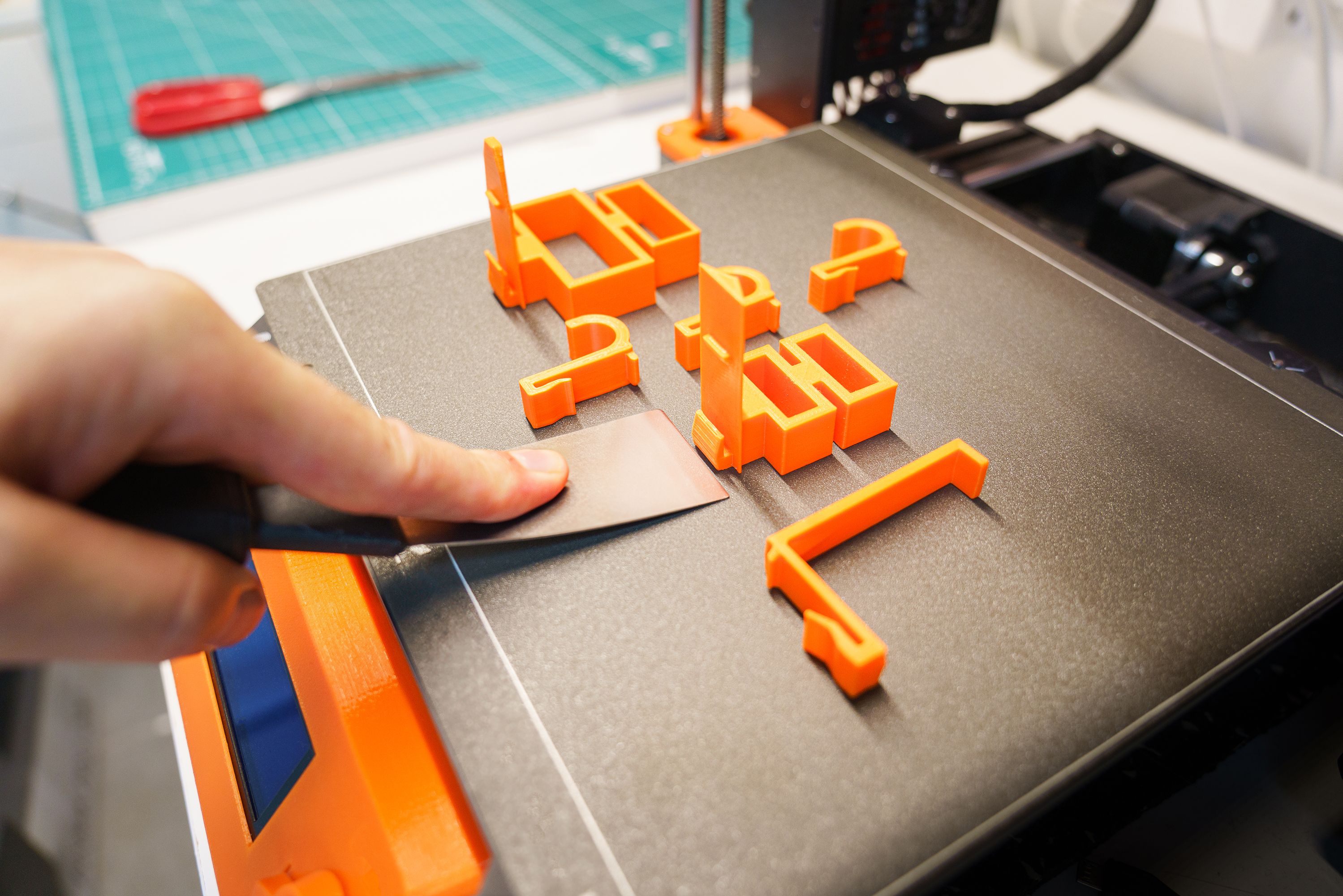
Once the print is complete, inspect the part and compare it with the intended dimensions and fit.
The slicer preview is one of the most useful tools in the entire process.
After selecting Slice in Cura or Slice Now in PrusaSlicer, switch to the layer preview.
Move the layer slider upward gradually and watch how the object will be built.
Look for several common problems.
- Missing details. Thin features may disappear when the slicer cannot produce them with the selected settings.
- Unsupported areas. Sections that begin printing in open air may require supports or a different orientation.
- Weak first layer. Very small contact areas may benefit from a brim.
- Unexpected gaps. Broken geometry may cause missing walls or strange toolpaths.
- Excessive supports. A different orientation may reduce material use and cleanup.
For example, rotating the cable holder by 90 degrees could create a large overhang that needs substantial supports. Returning its flat base to the print bed may eliminate much of that extra material.
Inspecting the preview takes only a short time and can prevent hours of wasted printing.
Step 8. Save the Project and Export the Print File
After checking the layers, save the slicer project before exporting the final print instructions.
PrusaSlicer can save a project as a 3MF file. Unlike an ordinary STL, the project can preserve printer settings, objects and other configuration details.
The Prusa 3MF documentation explains why the format is useful when returning to a project or sharing printing settings.
Export the generated G-code or another instruction format supported by your printer. Use the correct machine profile because print instruction files are not universally interchangeable between printers.
Transfer the file using the supported method, such as removable storage or a network connection.
Test the Smallest Useful Version First
Before printing a large or complicated object, consider producing a small test section containing its most difficult feature.
For a cable holder, print the retaining arm and a short section of the base. Check that the cable fits and that the arm behaves as intended.
If the opening is too narrow, adjust the geometry in Blender. If the print has rough overhangs, return to the slicer and examine the orientation or supports.
Keep the corrected Blender model and slicer project together. With both files saved, repeating the print or changing one dimension becomes much easier.
A reliable 3D printing process begins with accurate geometry and ends with a careful layer preview. The few minutes spent checking both are usually far cheaper than discovering a mistake halfway through a long print.